|
| |
| Position Sensor-KH Series | Rod style |
| KH Series —— Rod style |
|
|
|

|
|
|
■
|
Rugged Industrial Sensor
|
|
■
|
Linear, Absolute Measurement
|
|
■
|
Non-Contact Sensing Technology
|
|
■
|
Linearity Deviation Less Than ±0.01%
|
|
■
|
Superior Accuracy ,Resolution down to2µm
|
|
■
|
Repeatability Within ±0.001%
|
|
■
|
LED For Sensor Diagnostics
|
|
|
|
|
|
Interface
|
Analog
|
SSI |
start/stop |
| Output |
4~20mA; 0~10V
|
25, 24, 26 Binary/Gray |
RS422 |
| |
| Interface |
Profibus |
Canbus
|
Profinet
|
| Output |
Profibus - DP
|
Protocal: Basic / Open |
Profinet IO RT
|
| Stroke range |
25mm~7620mm |
| Accuracy |
Linearity Deviation<±0.01%F.S.,Repeatability<±0.001%F.S. |
| Installation |
M18x1.5 , 3/4" -16UNF-3A
|
| Protection |
IP67, Pressure rating: 35MPa / 70MPa peak
|
| Temperature |
Ordinary type:- 40℃~+85℃ ; High temperature type: - 40℃~+105℃ |
Voltage
|
Input : 24VDC (-15/+20%) , Polarity protection , Overvoltage protection |
| Magnet |
OD33; OD25.4; OD17.4; OD63.5
|
|
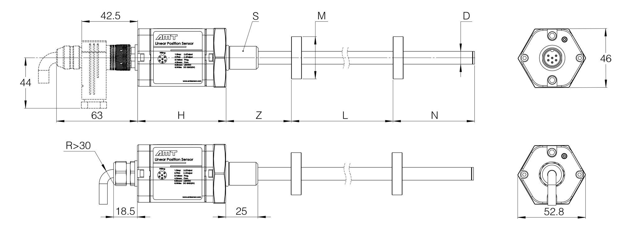
■ Dimensions
|
| |
|
|
| NO. |
Define |
Analog
|
SSI |
start/stop |
Profibus |
Canbus
|
| H |
Head length
|
68mm
|
78mm |
| Z |
Null Zone
|
50.8mm
|
| L |
Stroke Range
|
25mm~7620mm |
| N |
Dead Zone
|
63.5mm |
| D |
Rod O.D |
7mm ; 8mm ; 10mm ; 12mm
|
| M |
Magnet O.D.
|
OD17.4 ; OD20 ; OD25.4 ; OD33; OD63.5 |
| S |
Thread
|
M18x1.5 |
|
■ Wiring & Diagnostic Display
|
Interface:Analog
|
Analog
|
Pin
|
Cable
|
Define
|
LED
|
Status
|
Define
|
|

|
1 |
GY
|
Output Signal
|

|
GN ON
|
Normal function |
| 2 |
PK |
DC GND
|
GN flashing
|
On communicating |
3
|
YL |
Reserved
|
RD flashing
|
Magnet out of setup range |
| 4 |
GN |
Reserved
|
RD ON
|
Magnet not detected |
| 5 |
BN |
+24VDC(-15%/+20%)
|
|
|
| 6 |
WT
|
DC GND (0Vdc)
|
|
|
Interface:SSI
|
SSI
|
PIN
|
Cable
|
Define
|
LED
|
Status |
Define |
|

|
1
|
GY
|
Data (-)
|

|
GN ON
|
Normal function |
|
2
|
PK
|
Data(+)
|
GN flashing |
On communicating |
|
3
|
YL
|
Clock(+)
|
RD flashing |
Magnet out of setup range |
|
4
|
GN
|
Clock (-)
|
RD ON |
Magnet not detected |
|
5
|
BN
|
+24VDC(-15%/+20%)
|
|
|
|
6
|
WT
|
DC GND (0Vdc)
|
|
|
| 7 |
--- |
N.C. |
|
|
Interface : Start/Stop
|
Start/Stop
|
PIN
|
Cable
|
Define
|
LED
|
Status |
Define |
|
|
1
|
GY
|
Stop (-)
|
|
GN ON
|
Normal function |
|
2
|
PK
|
Stop (+)
|
GN flashing |
On communicating |
|
3
|
YL
|
Start (+)
|
RD flashing |
Magnet out of setup range |
|
4
|
GN
|
Start (-)
|
RD ON |
Magnet not detected |
|
5
|
BN
|
+24VDC(-15%/+20%)
|
|
|
|
6
|
WT
|
DC GND (0Vdc)
|
|
|
| |
|
|
|
|
Interface : Profibus - DP
|
C53
|
PIN
|
Cable
|
Define
|
LED1
|
Status
|
Define
|
|
 left left
 right right
|
1
|
—
|
VP+5N(For Termination)
|

|
GN ON
|
Normal function
|
|
2
|
GN
|
RxD/TxD-N
|
GN flashing
|
On communicating
|
|
3
|
—
|
DGnd(For Termination)
|
RD flashing
|
Magnet out of setup range
|
|
4
|
RD
|
RxD/TxD-P
|
RD ON
|
Magnet not detected
|
|
5
|
---
|
|
|
|
|
|
PIN
|
Cable
|
Define
|
|
|
|
|

|
1
|
BN
|
+24VDC(-15%/+20%)
|
|
|
|
|
2
|
WT
|
N.C.
|
|
|
|
3
|
BU
|
DC GND (0Vdc)
|
|
|
|
4
|
BK
|
N.C.
|
|
|
|
|
|
|
|
|
|
D62
|
PIN
|
Cable
|
Define
|
LED
|
Status
|
Define
|
|
 left left
 right right
|
1
|
GN
|
RxD/TxD-N
|

|
GN ON
|
Normal function
|
|
2
|
RD
|
RxD/TxD-P
|
GN Flashing
|
On communicating
|
|
3
|
—
|
DGnd(For Termination)
|
RD Flashing
|
Magnet out of setup range
|
|
4
|
—
|
VP+5N(For termination)
|
RD ON
|
Magnet not defected
|
|
5
|
BK
|
+24VDC(-15%/+20%)
|
|
|
|
6
|
BU
|
DC GND(0VDC)
|
|
|
|
—
|
—
|
|
|
|
Interface : Profinet
|
C53
|
PIN
|
Cable
|
Define
|
LED1
|
Status
|
Define
|
|

|
1
|
YL
|
Tx+
|

|
GN ON
|
Normal function
|
|
2
|
WT
|
Rx+
|
GN Flashing
|
On communicating
|
|
3
|
OG
|
Tx-
|
RD Flashing
|
Magnet out of setup range
|
|
4
|
BL
|
Rx-
|
RD ON
|
Magnet not defected
|
|
5
|
—
|
——
|
YL Flashing
|
Bus connection failure
|
|
|
PIN
|
Cable
|
定义
|
LED2/3
|
Status
|
定义
|
|
|
1
|
BN
|
+24VDC(-15%/+20%)
|
|
GN ON
|
Ethernet activation
|
|
2
|
WT
|
N.C.
|
GN OFF
|
Ethernet disconnected
|
|
3
|
BU
|
DC GND(0VDC)
|
|
|
|
4
|
BK
|
N.C.
|
|
|
|
|
|
|
|
|
Interface : Canbus
|
C53
|
PIN
|
Cable
|
Define
|
LED1
|
Status
|
Define
|
|
left
right
|
1
|
WT
|
Shield
|
|
GN ON
|
Normal function
|
|
2
|
BN
|
N.C.
|
GN flashing
|
On communicating
|
|
3
|
BU
|
N.C.
|
RD flashing
|
Magnet out of setup range
|
|
4
|
BK
|
CAN (+)
|
RD ON
|
Magnet not detected
|
|
5
|
GY
|
CAN (-)
|
|
|
|
|
PIN
|
Cable
|
Define
|
|
|
|
|
|
1
|
BN
|
+24VDC(-15%/+20%)
|
|
|
|
|
2
|
WT
|
N.C.
|
|
|
|
3
|
BL
|
DC GND (0Vdc)
|
|
|
|
4
|
BK
|
N.C.
|
|
|
|
|
|
|
|
|
|
D62
|
PIN
|
Cable
|
Define
|
LED
|
Status
|
Define
|
|
left
right
|
1
|
GY
|
CAN (+)
|

|
GN ON
|
Normal function
|
|
2
|
PK
|
CAN (-) |
GN Flashing
|
On communicating
|
|
3
|
YL
|
N.C.
|
RD Flashing
|
Magnet out of setup range
|
|
4
|
GN
|
N.C.
|
RD ON
|
Magnet not defected
|
|
5
|
BN
|
+24VDC(-15%/+20%)
|
|
|
|
6
|
WT
|
DC GND(0VDC)
|
|
|
|
—
|
—
|
|
|
|
|
|
|